Building a Guitar Pedal Prototype with a Feather
We're fans of the Adafruit Feather M4 Express microcontroller for its speed, good mix of features, and easy programming with Arduino tools. So, naturally, we thought: should we make a guitar pedal with it? Of course we should make a guitar pedal with it. And so we did. There were some problems along the way, but it worked out pretty well in the end. In this post, I'll walk though how we did it.
The first thing to do was to choose an audio codec. The Teensy Audio Adaptor Board, with its SGTL5000 chip and supporting components already installed, seemed like a good starting point.
Next, we needed to make all the necessary connections for the Feather to control the SGTL5000, which is mostly done over I2S. We worked out a mapping of which Feather pins need to be connected to which Audio Board pins:
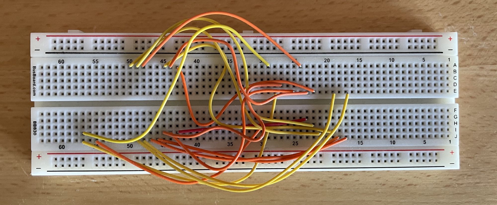
Then we wired everything up on a breadboard to try it out:
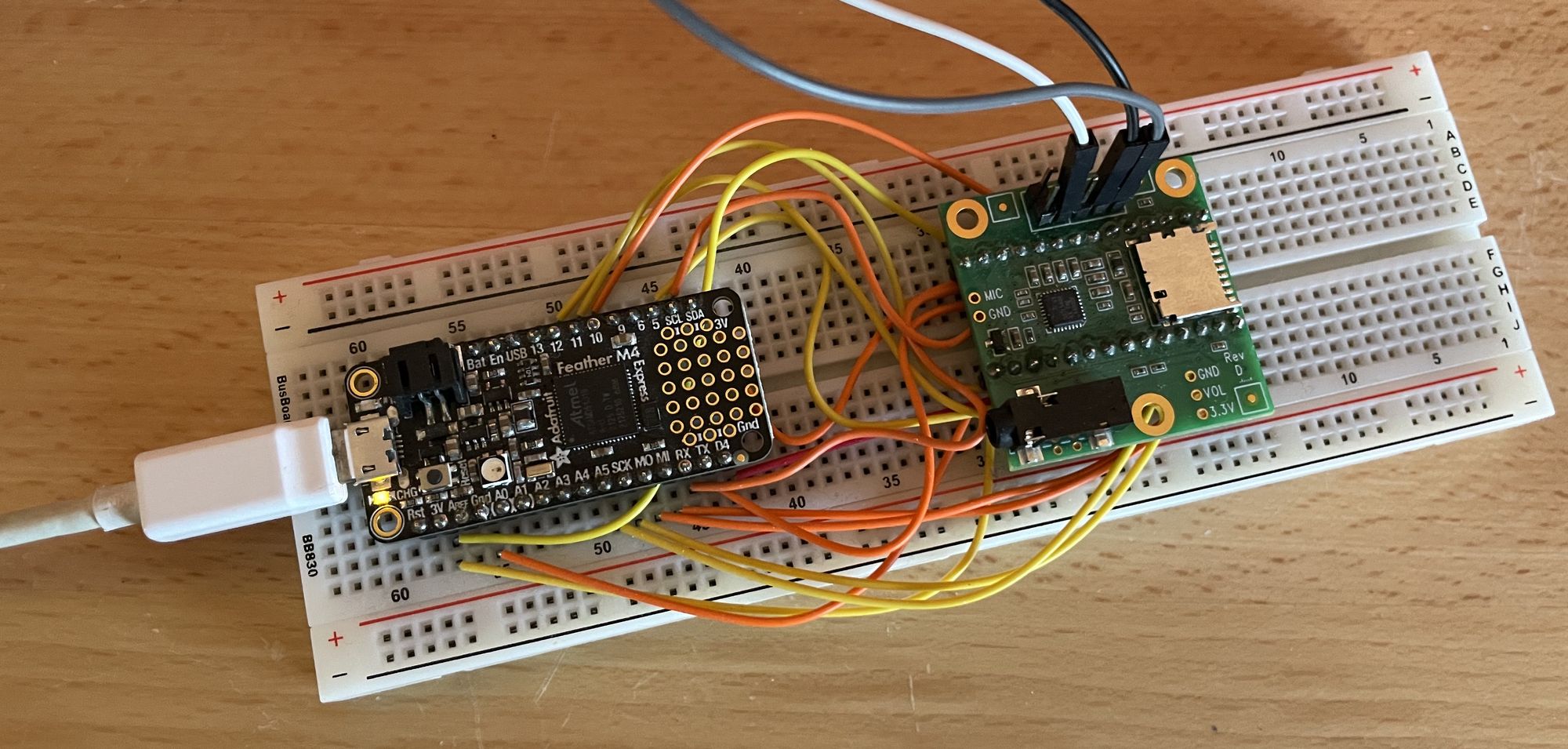
After correcting a couple wiring mistakes and fixing an issue we ran into in the Adafruit port of the Teensy Audio library, we had it working! Unfortunately, the sound wasn't great.
Below is an audio test I did with the Feather programmed to just pass audio straight from the SGTL5000 input to its output (using the Audio library's PassThroughStereo example). The first two tones you'll hear are the normal guitar sound straight into the amplifier, bypassing the device. After the click, the second two tones demonstrate the effect our device had on the sound:
As you can hear, there was some buzzing distortion added to the sound. So what was going on?
Well, it took a while to figure out, but the problem was with using Adafruit's ZeroI2S library to provide clock signals for the SGTL5000. ZeroI2S was written with specific clock rates in mind, and the combination of the clock rates available on the Feather M4 and the ones needed by the SGTL5000 were a bad fit. The library wound up running MCK and SCK at rates that didn't work together. I came up with a fix for the way clock dividers are calculated in the ZeroI2S library, and that cleaned the sound up.
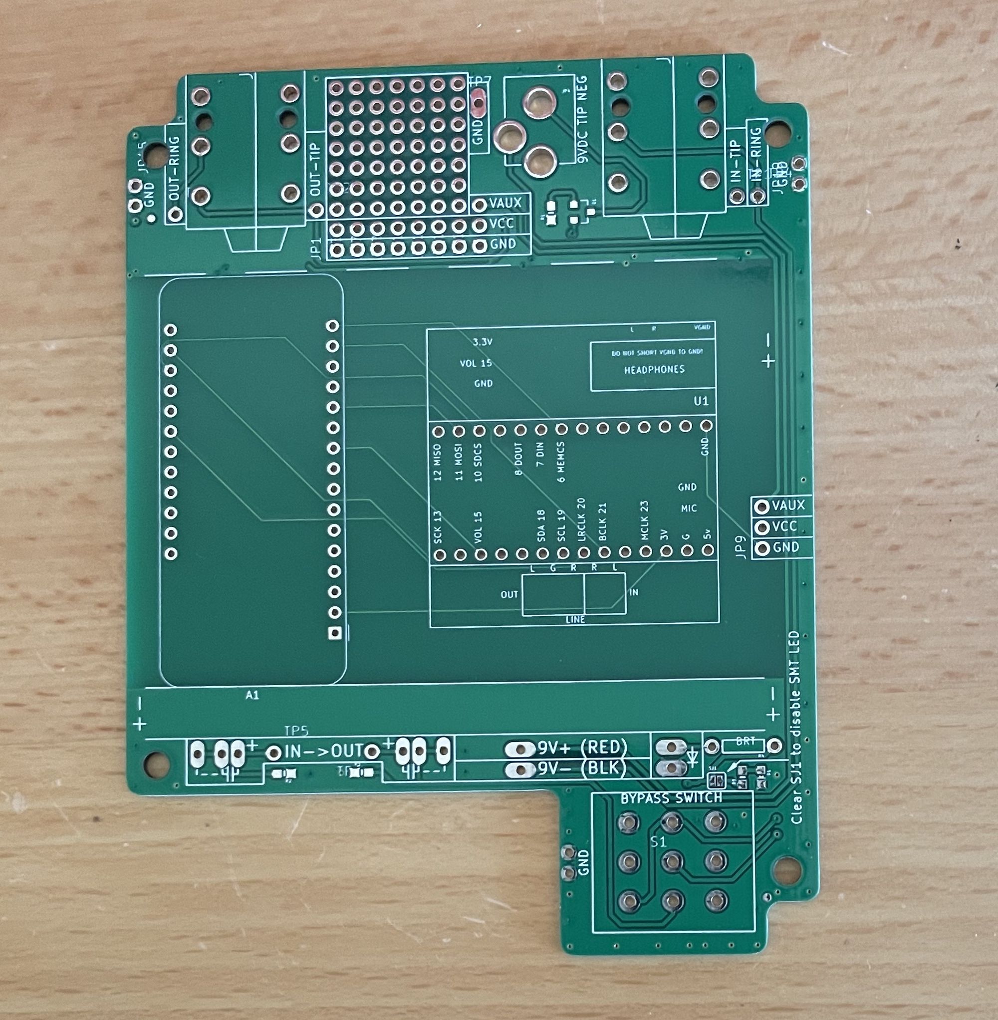
With everything working on the breadboard, it was time to make a PCB so that we can eventually fit this thing into a pedal enclosure. We started with the board for the SparkFun Proto Pedal, which has some pedal basics already set up, and dimensions that seemed about right for this project. The Proto Pedal has been discontinued, but SparkFun were nice enough to make the EAGLE files available open source. We find KiCad easier to use, so we converted the files, and somewhat crudely deleted things from the Proto Pedal to make room. After importing footprints for the Feather and Teensy Audio Board, we laid out the traces, and had some PCBs made. It took a few tries to get it right, but eventually we wound up with this:
As an aside, this was my first time getting a PCB made. If you haven't done it before, doing a CAD drawing on your laptop and having someone mail it to you as a circuit board you can hold in your hand is kind of magical.
Anyway, I soldered pin header sockets to one of the boards so that I could slot in the Feather and Audio Board to check that it worked (without needing to desolder them if it didn't):
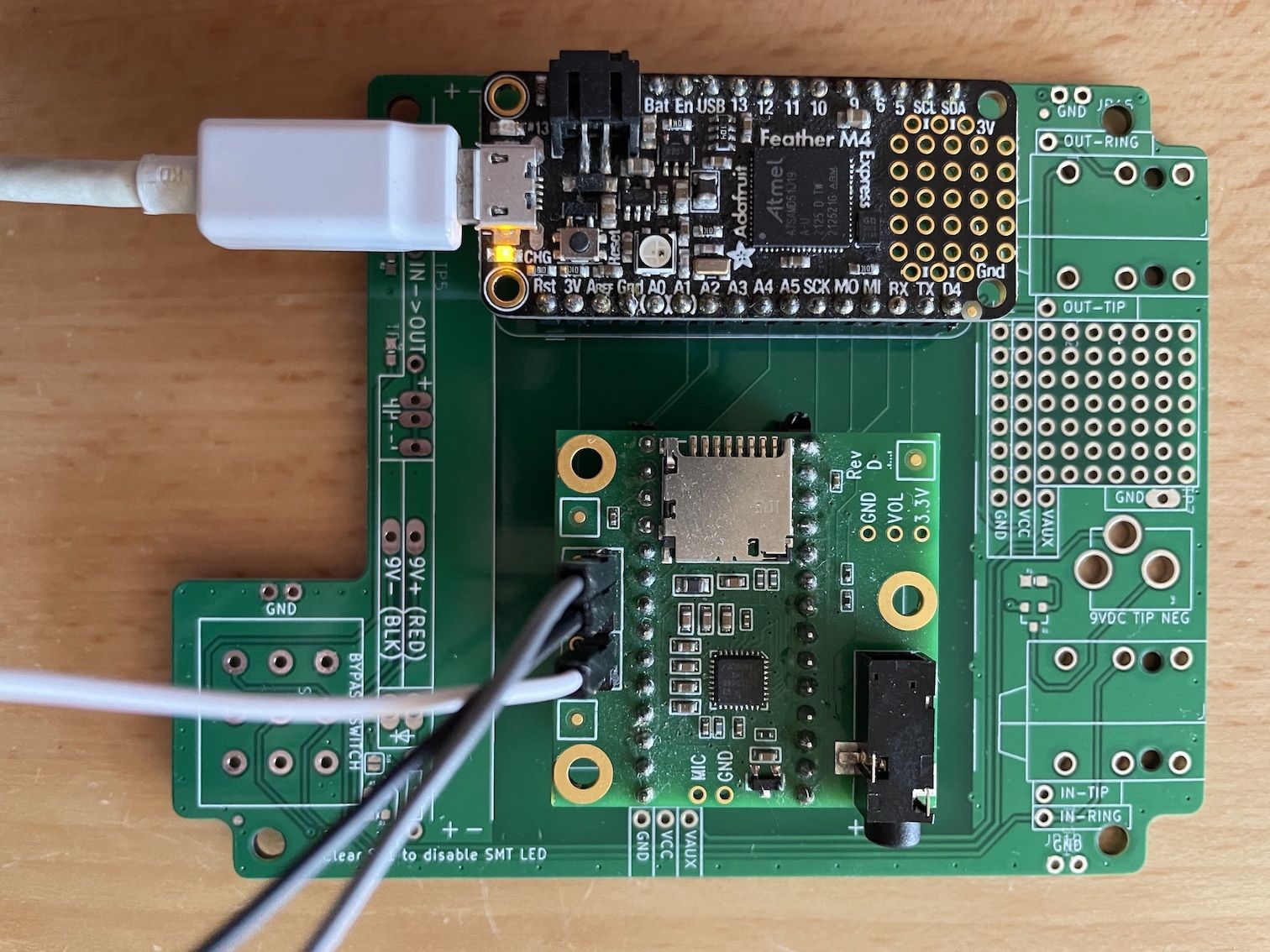
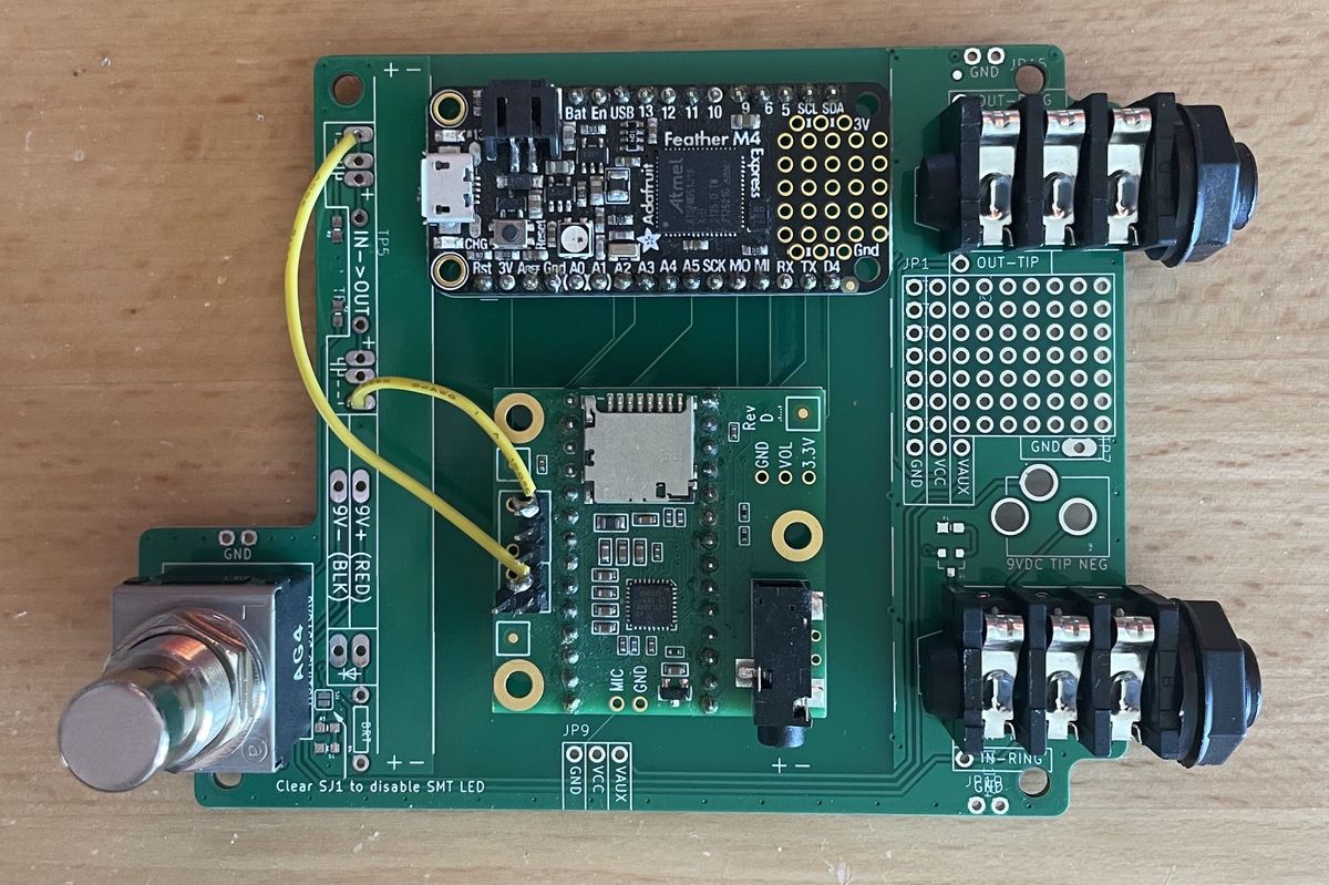
It worked! (Well, okay, it worked this time, because I've skipped past the failed attempts.) Alas, comparing the height of the boards on their sockets to the height of a stomp switch, it was clear that to get everything to fit in a pedal enclosure it would be necessary to solder the pins directly through the PCB. Having confirmed that the board layout was right, I went for it, and also added the jacks, stomp switch, and connections for the audio input and output. You've seen this stage before, at the top of the page, but I can't resist showing it off again:

All we needed now was a guitar effect. Some of the Audio library examples worked for us, but we wanted to start from scratch and make some effects from the ground up. So, we thought, what's the simplest guitar effect? We figured tremolo is about as simple as it gets: just use an LFO to turn the volume up and down.
You can check out the code in the GitHub repo. Very briefly, here are the most interesting parts: tremolo.ino is where we connect up the I2S audio input, the tremolo effect, and the I2S output (using a mixer to make a depth control), and set up the volume, and the depth and speed of the tremolo. The guts of the tremolo effect itself are in effect_tremolo.cpp. I tried to provide some helpful comments in that file. If you're interested in the details, I've written another post getting into how the code works.
Here it is in action:
I'd call that a successful proof of concept. To really work as a pedal, it still needs an enclosure, and some knobs to control effect parameters, and a pedal-style power supply so that it doesn't have to be powered from USB. But those things will be straightforward enough. It's a start!
If you've made it this far, I'm guessing there's a chance you might be interested in building something like this yourself. If so, that is very cool, and you can reach out to us at blacklightunicorn at gmail. We'll be happy to send you a PCB and give you some pointers.