Feather Guitar Pedal, Part 2: Knobs, Switches, and Power
When I ended my previous post about our prototype guitar pedal based on the Adafruit Feather M4 Express, it was working, but still needed a pedal-style power supply, and knobs to control effect parameters. I'll get to all of that in this post, but first, I wanted to give some tips on sourcing parts that fit the boards, for those of you who have decided to build one.
- For power (when not powering from USB during testing), you'll need a DC barrel jack. The board was designed to fit the one from SparkFun but Adafruit sells one that fits as well.
- For the stomp switch, there are a bunch of different PCB-mount footprints out there, but the only one I've found that fits is the one SparkFun sells. You can also get it from Mouser or DigiKey by searching for the part number, COM-15133. If I do another version of the PCB, I'm going to try to make it adaptable to some other models of stomp switch.
- Jacks are fortunately more standard. The SparkFun part is out of stock as I write this (Mouser still has some, part COM-11144), but Amphenol ACJS-MHOM fits, as does Neutrik NRJ6HH (with NRJ-NUT-B and NRJ-WB).
- The final thing to figure out is an enclosure. The Proto Pedal enclosures are no longer made, but there may still be a few floating around if you search. You can drill your own, of course. I haven't tried it, but I suspect a Hammond 1590BB is a good starting point. The dimensions in the Proto Pedal mechanical drawings should provide a good guide for this board.
With that out of the way, let's add some knobs to control effect parameters!
Let's Add Some Knobs to Control Effect Parameters 🎛️
The concept here is simple: the Feather has 6 10-bit ADC (that's "Analog to Digital Converter") pins, named A0 through A5, where we can supply a voltage between 0V and 3.3V, and we can read the pin with the analogRead function and get an integer ranging from 0 to 1023 (the range of numbers that can be represented with 10 bits). Then we convert that into our parameter value. To control the volume, for example, we might interpret 0 to mean silence, and 1023 to mean full volume. Half volume would be around 512.
How do we supply that voltage? Just use a potentiometer as a voltage divider: one side is wired to ground, the other side is wired to the Feather's 3.3V power pin, and the middle "wiper" connector is wired to an ADC pin.
For our tremolo effect, the relevant parameters are the speed and depth of the effect, and the overall output volume, so we'll need three knobs. That's a good number that will provide decent flexibility for a lot of effects.
Also, because of the way the tremolo effect was written, it would be easy to have it do both square and sine (-ish) waveforms, both useful varieties of tremolo, so we can also wire up a switch to control that. It'll work a lot like a potentiometer, but instead of selecting any voltage in the range, one side of the switch will connect the ADC pin to 0v, and the other side will connect it to 3.3V, giving us just 0 or 1023 when we read the pin.
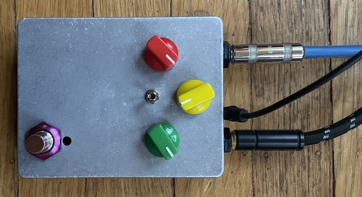
I started with a Proto Pedal enclosure, and added the knobs and switch:
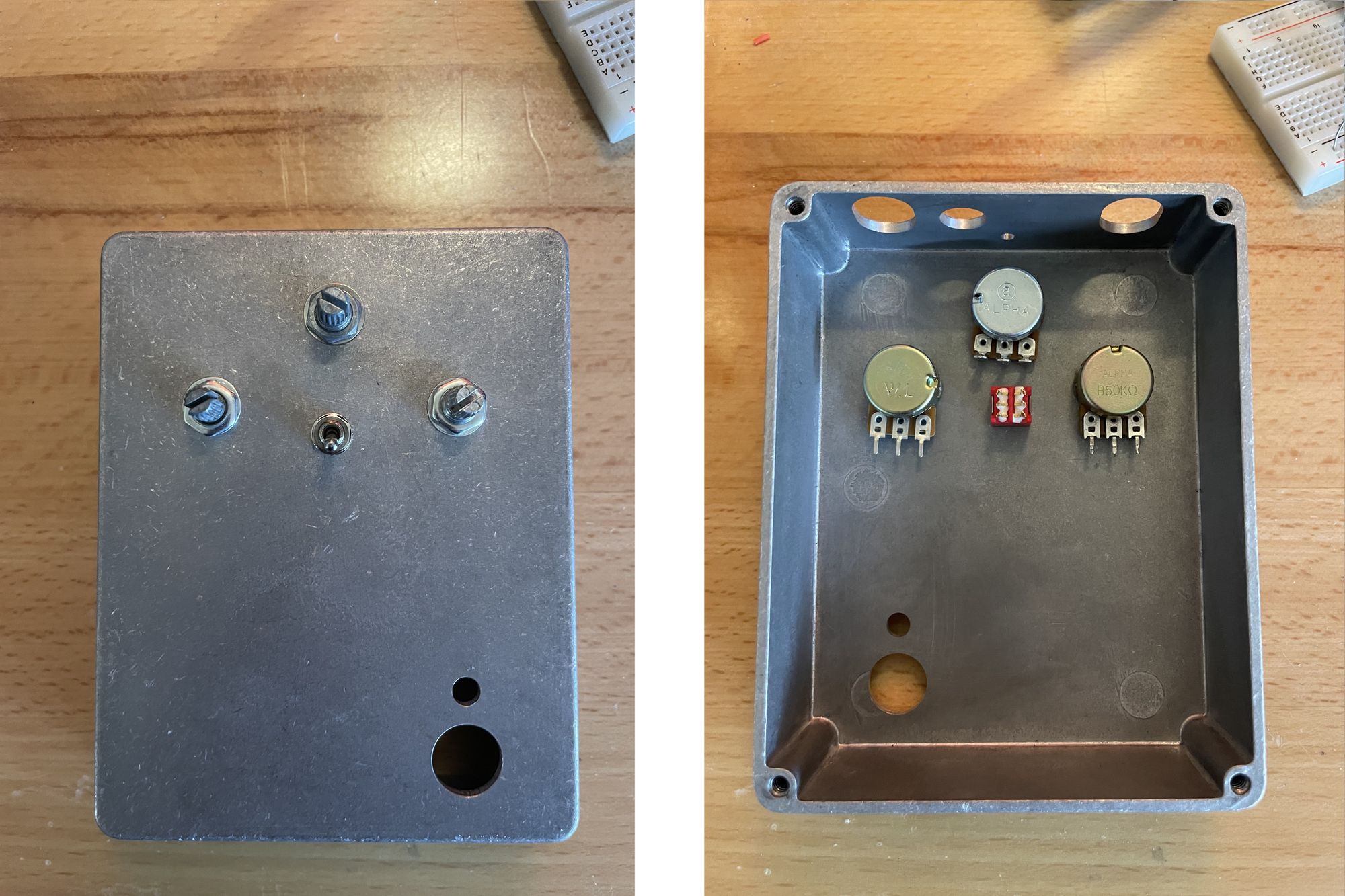
The choice of potentiometer values isn't very sensitive, as long as they're at least 10k (which would be a pretty standard choice here). I used 50k pots, and a 2M audio-taper pot for the volume, because that's what I had handy. The switch is a DPDT On-On, but as you'll see, for our purposes a SPDT On-On switch would have been fine. The most important aspect in choosing all of these parts was to find parts that didn't extend too deep into the enclosure, because we need room for the board to fit behind them.
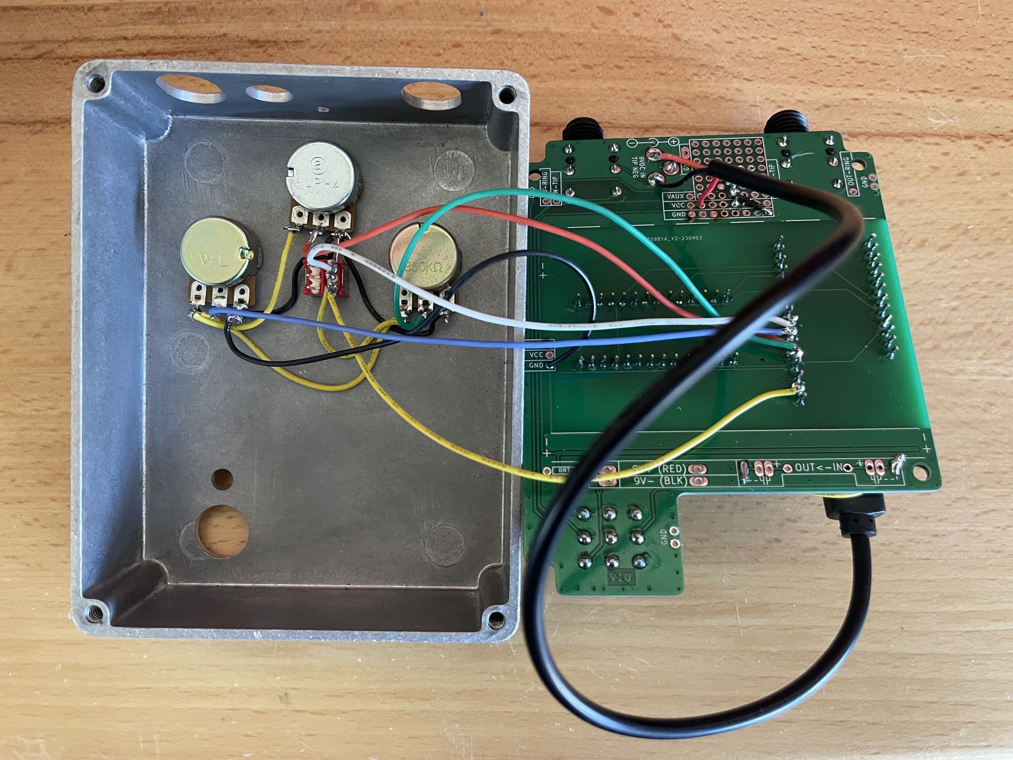
Anyway, with parts selected and installed, I wired everything up:
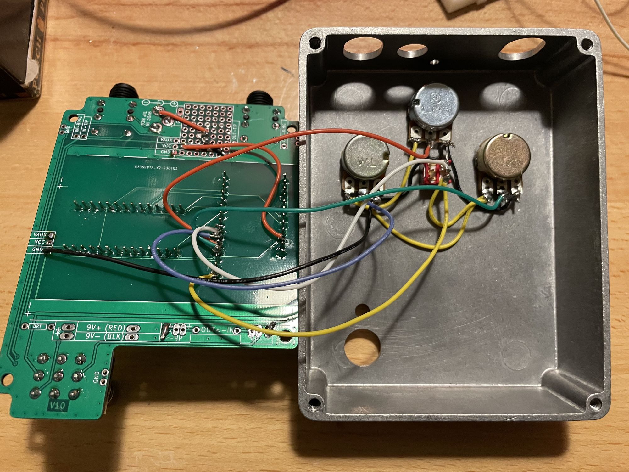
It's a little bit hard to see what's going on there, but it's not too complicated:
- The left side of every potentiometer, and the bottom post on the switch (I'm only using the right side) are daisy-chained to each other, and ultimately connect back to the 3.3V pin on the Feather.
- The right sides of the pots, and the top post on the switch, are also daisy chained together, and wired to the GND hole on the PCB.
- The center posts of the pots and the switch are each individually wired to ADC pins on the feather. The pots, from left to right (as above, looking at the back of the pedal), connect to
A2,A1, andA0. The switch connects toA3.
And that's it! Here's how we read and convert the speed value in code:
float speed = analogRead(A0) / 1023.0;
Diving by 1023.0 gives us a floating point value ranging from 0 to 1. I've updated the code, and you can see all the details for the other parameters in the GitHub repo.
⚡ Power ⚡
At this point, the whole thing is just about ready to close up and use, except that up to now it's been powered from USB. We need to be able to plug it into a pedal power supply. The board has a place for a pedal-standard 9V barrel jack, but the Feather needs 5V. So first of all, we need to turn 9V into 5V. No problem, right? 5V linear regulator, problem solved?
Well, it's not so easy. The Feather is already going to be on the power-hungry side for a pedal, and something like a 7805 linear regulator is only about 56% efficient converting 9V to 5V, meaning the regulator will use almost as much power as the Feather! We really want an efficient regulator, which means we want a switching regulator.
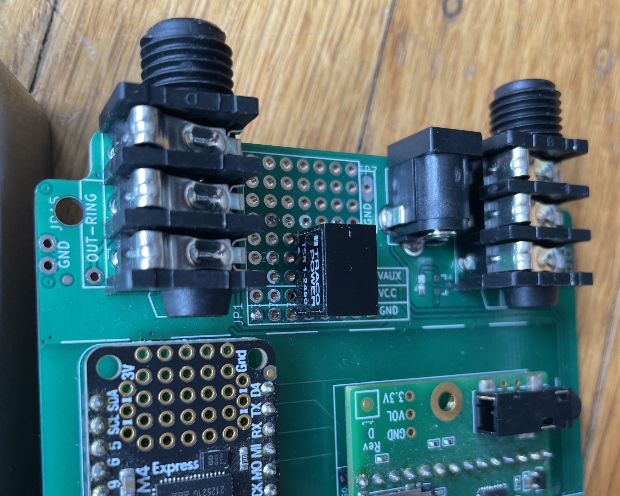
After looking around, I settled on the Traco Power TSR 1-2450. It's 94% efficient, and comes in a simple 3-pin through-hole package, just like a linear regulator. Okay, maybe it was so easy after all.
The next issue is how to connect our new power supply to the board. Adafruit recommends USB or battery power for the Feather and has this to say about supplying 5V with an external supply:
Connect an external 5V power supply to the USB and GND pins. Not recommended, this may cause unexpected behavior when plugging in the USB port because you will be back-powering the USB port, which could confuse or damage your computer.
I'm not sure how many USB ports are out there that would be damaged by finding 5V on the power line, but better safe than sorry. So, we need to prevent plugging in a USB cable when supplying the power. Well, there's a simple, fool-proof way to ensure this can't happen: supply the power through a USB cable. That way, if we want to connect USB to program the pedal, we're going to have to take the pedal power cable out of the USB port to do it.
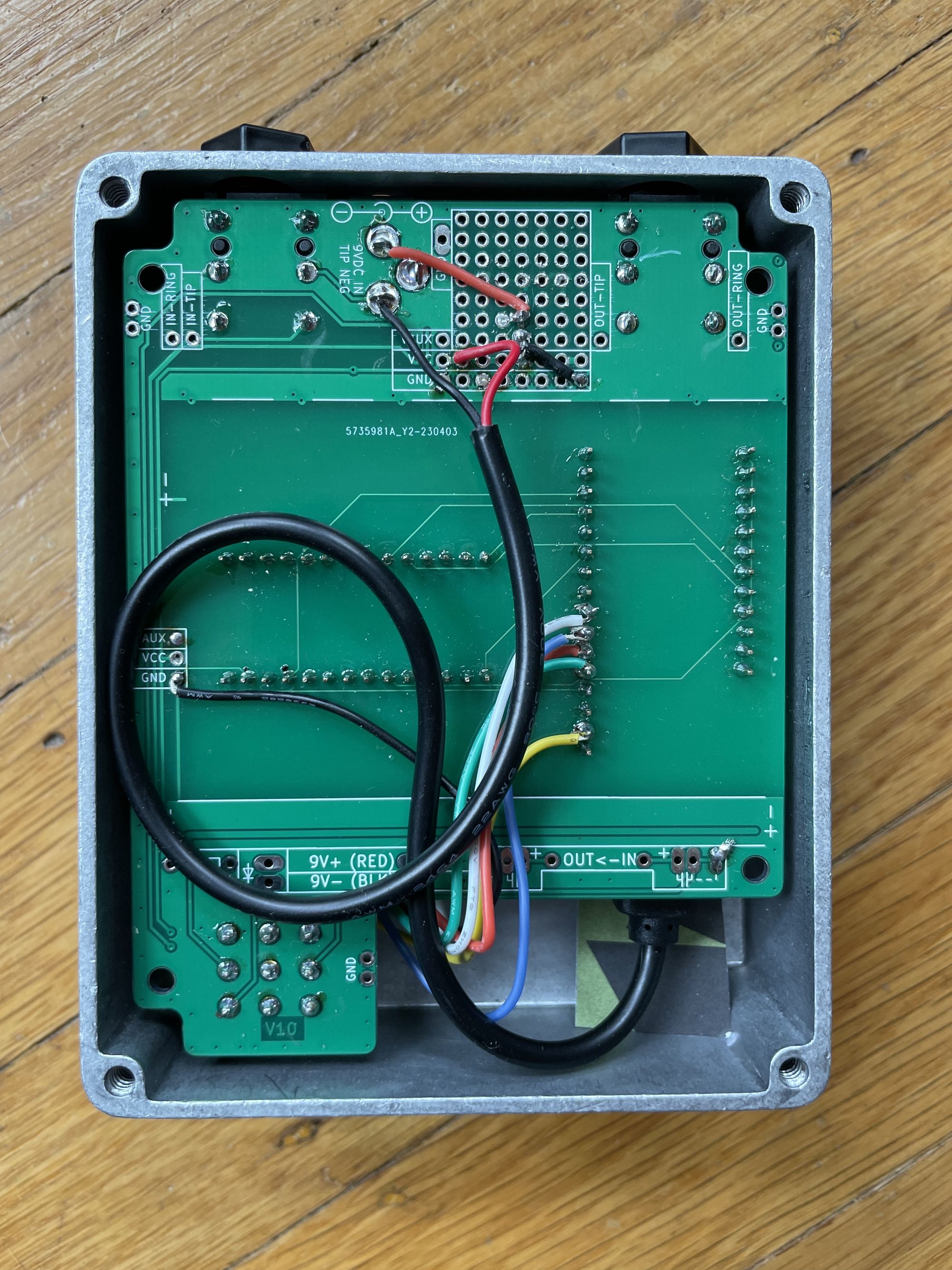
So our final design connects the +9V pin of the barrel jack to pin 1 of the TSR 1-2450 (the input), ground to pin 2, and pin 3 (the output) and ground to each of the two leads of a micro USB power pigtail connector:
By the way, on the other end of the barrel jack you'll need a 9V pedal power supply, meaning it needs to have center-negative barrel plug. That center-negative standard is different from most 9V plugs, so watch out. Also, because this is a digital pedal it's best to use something that can supply at least 250mA, maybe 300mA to be safe. Running the tremolo effect will probably use less than 100mA, but more complex effects will work the Feather's CPU harder and use more power.
Okay, nothing left now but to put it together and try it out!
I found getting the thing into the enclosure a little bit challenging. To fit the stomp switch while the jacks are already in place requires bending the board a little bit, which doesn't seem at first like it's going to work, but it does.
Almost ready to close it up:
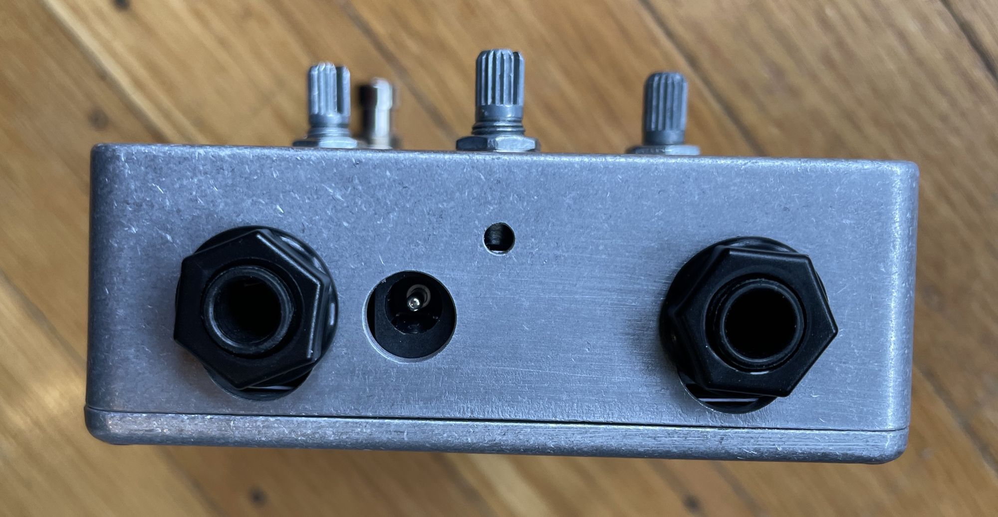
Looking a lot more like a pedal now! Here's a quick demo:
The buzzing noise floor you hear is from my amp, not the pedal. I was a little worried that the switching regulator might introduce too much noise, but so far I'm pretty happy with the noise floor.
What's next? Well, I should have added an LED to indicate when it's engaged! I also learned some lessons putting this together. I mentioned working with other stomp switch models, and I think I could also make it a little bit easier to assemble, and improve the enclosure. Also, while it was a nice starting point, tremolo is not the most exciting effect. Maybe I'll attempt a pitch shifter. If I'm brave, maybe I'll attempt it in Brandon's language-in-progress, Bell. Stay tuned!